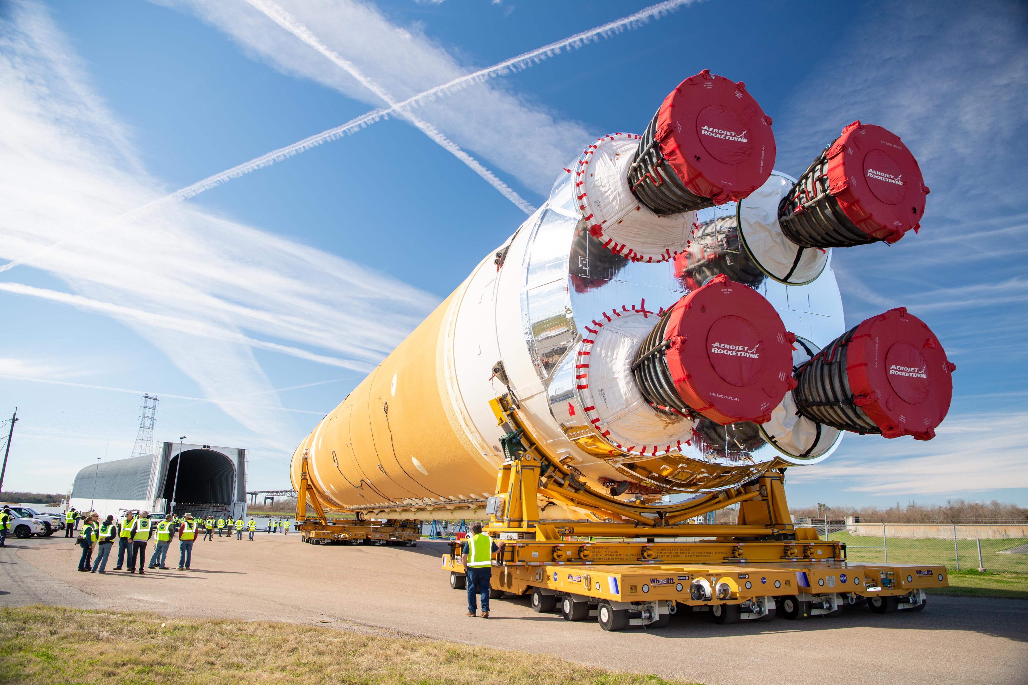
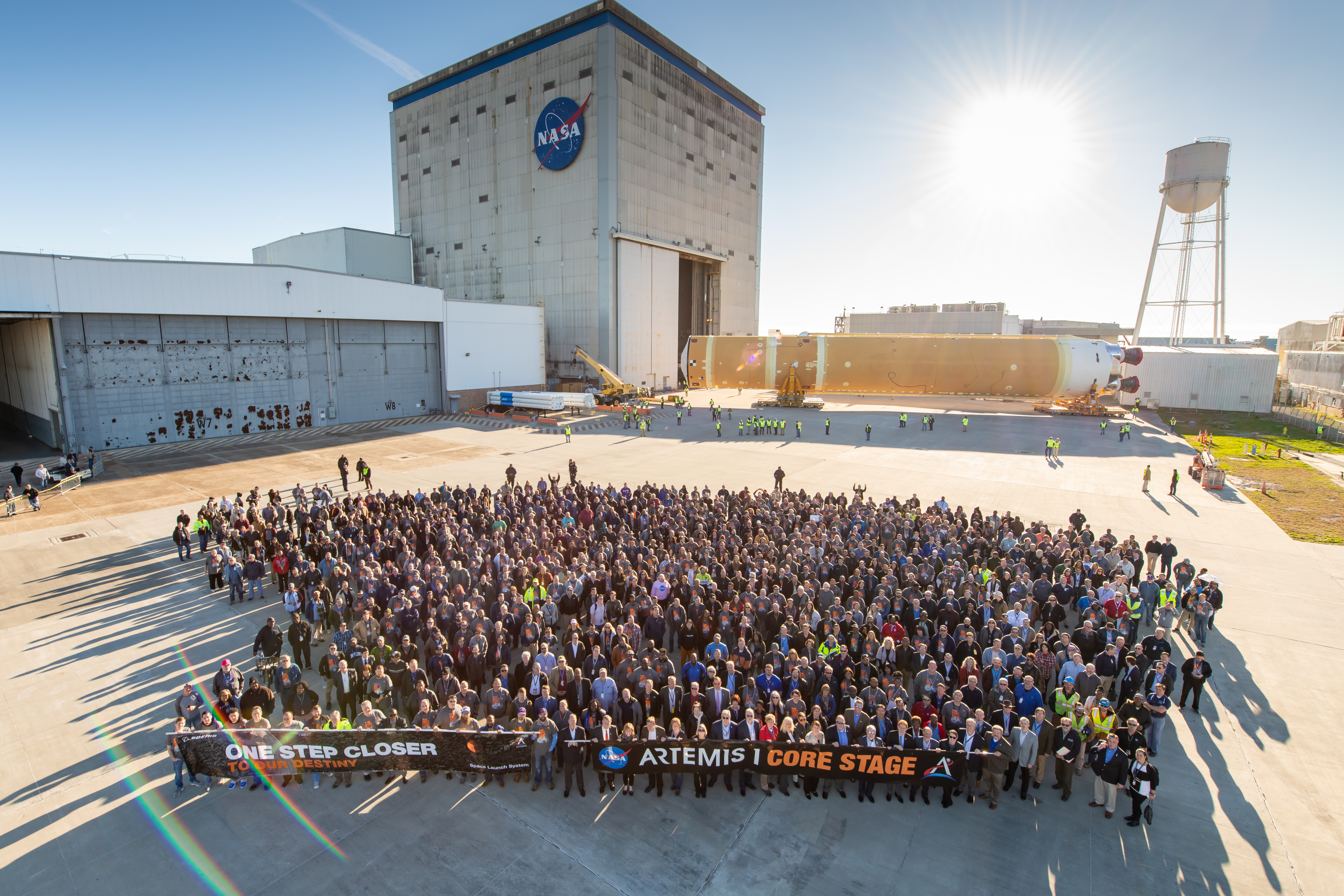
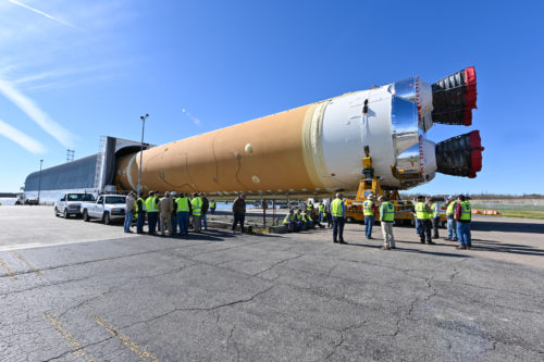
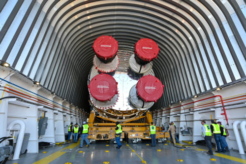
On Wednesday, NASA and its Space Launch System (SLS) partners reached a major milestone with the completion and roll out of the 212 foot (64.62 m) long Artemis 1 SLS Core Stage from the agency’s Michoud Assembly Facility (MAF), loading it onto the Pegasus barge for delivery to nearby Stennis Space Center where it will soon begin a major testing campaign, before being sent to Florida next year for its inaugural launch from Kennedy Space Center’s pad 39B to send Orion around the moon & back home.
For those who brought the SLS from concept to a reality, it must bring a well-earned sense of fulfillment and accomplishment.
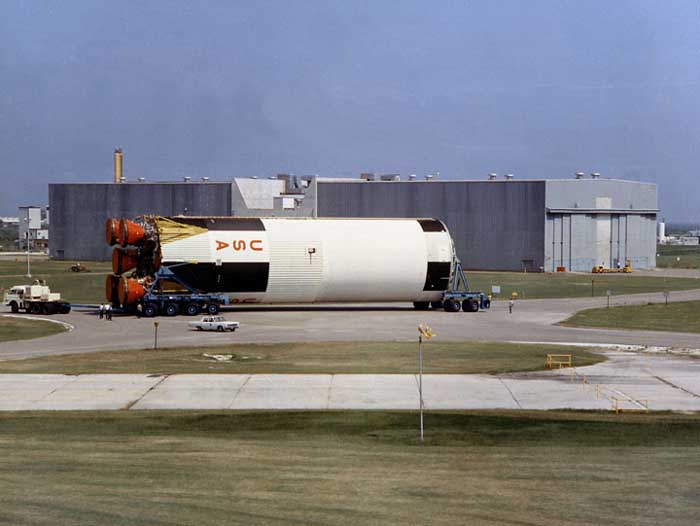
With NASA’s history of designing and building the 365 foot Saturn V, it is understandable that some may wonder how hard could it could have been to build the Space Launch System. After all, Boeing, which is building the SLS Core Stage at Michoud Assembly Facility, also built the Saturn V S-1C first stage at the same location. And the SLS uses two solid boosters and four RS-25 liquid oxygen (LOX) and liquid hydrogen (LH2) engines, abbreviated as LOX/LH2, all of which were developed for the Shuttle program. So isn’t it the case that we already know how to build the SLS? If only knowledge and experience could so easily be preserved and conveyed between generations.
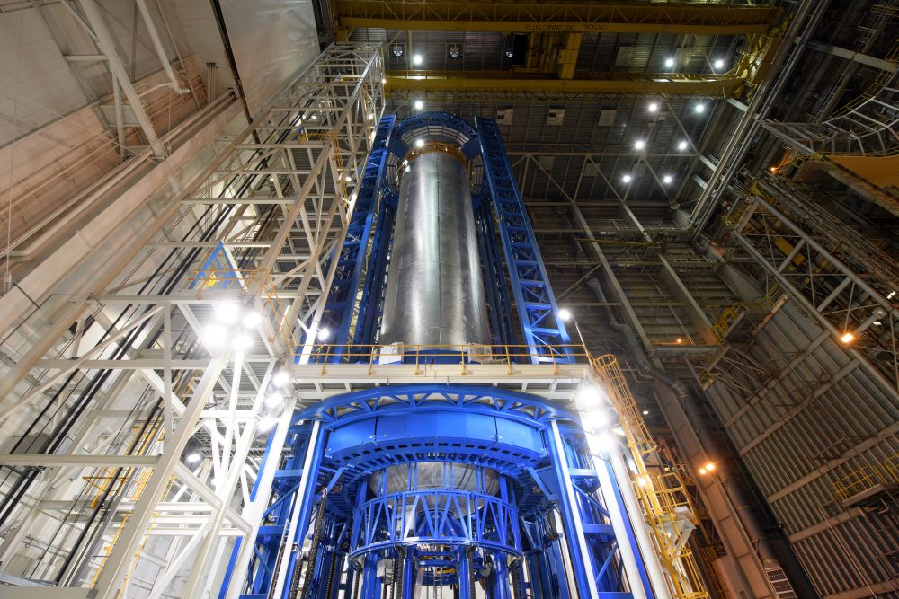
The Space Launch System (SLS) program began on September 14, 2011. In the ensuing 8 years, the SLS program technicians, engineers and managers have overcome difficulties that NASA and its SLS contractors never foresaw. Some of those challenges arose because of how motors and engines are arranged on the rocket, others because nobody had ever stir friction welded such thick panels of aluminum 2219, or because nobody had ever built a 175 ft (53.34 m) vertical stir friction welding and inspection unit on land that was once a bayou.
As with any engineering endeavor, the challenges presented to the SLS managers, engineers, and technicians, while causing a two year delay in finishing the SLS Core Stage 1, were none-the-less solved, and those solutions will pay dividends in shorter build-times and increased efficiencies for SLS core stages currently in production and those to follow.
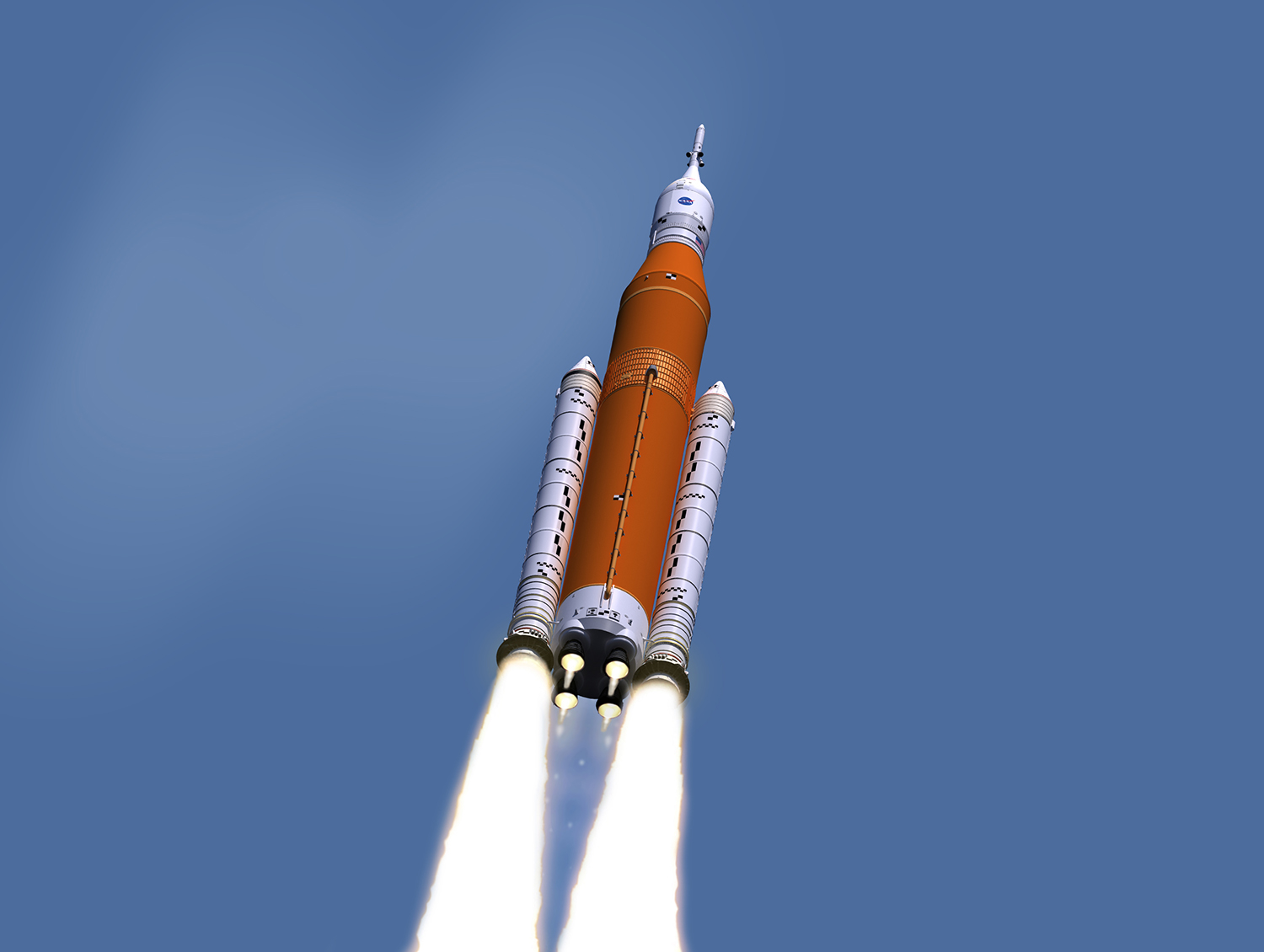
There are significant differences from the Space Shuttle and SLS. When looking at the two solid rocket motors on each side, one probably doesn’t notice that the SLS solid rocket boosters (SLS SRB) are larger than those on the Space Shuttle because they have five segments to each of the Shuttle solid rocket booster’s (SRB) four. The extra segment and other even less noticeable advances mean that the SLS solid rocket boosters each produce 3.6 million lbf (16,014 kN) to the Shuttle SRB’s 2.8 million lbf (12,455 kN).
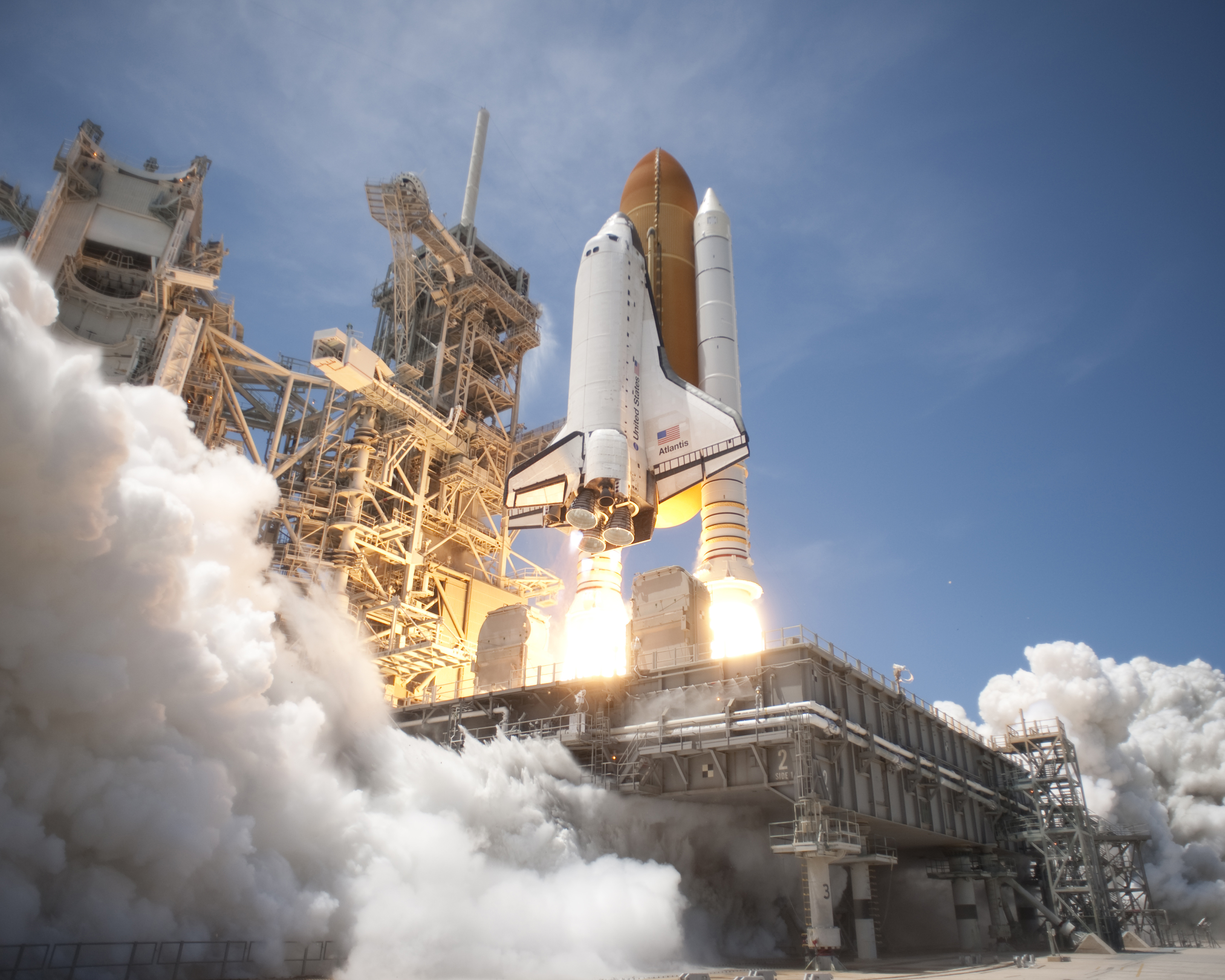
Another difference that may go unnoticed is how close the four RS-25 engines are to the more powerful SLS SRB’s. This means those engines are operating in an environment with much more heat–the exhaust of the 5-segment SRB’s is 4,500 F (2,482 C)–and acoustic energy than those same engines operated within on the Space Shuttle.
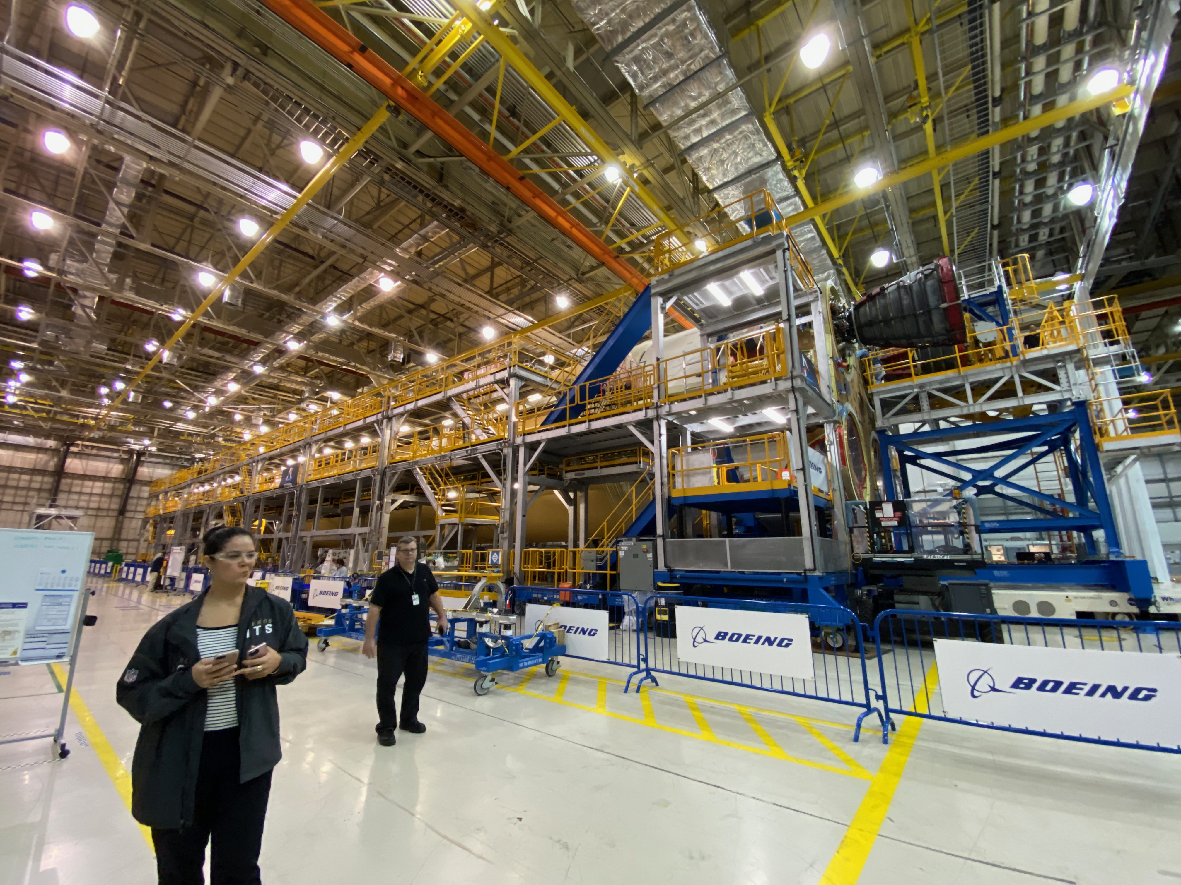
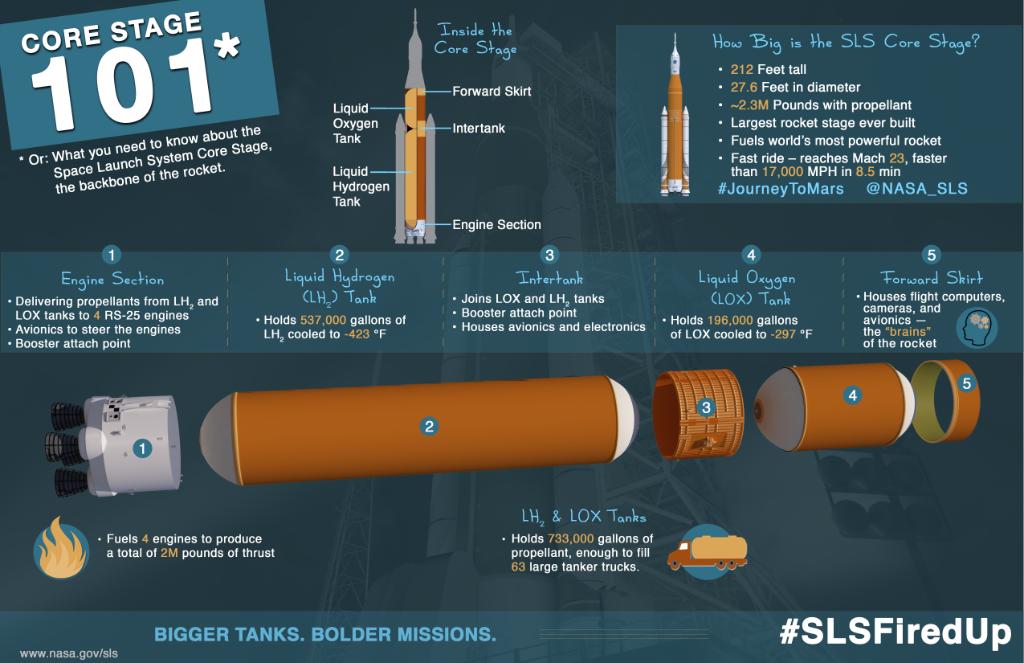
The way the SLS Core Stage is assembled is another change from the Saturn V and Shuttle External Tank. When engineers conceived of how to manufacture the SLS, the thinking was to assemble it as were the Saturn V S-1C and Shuttle ET, that is vertically. But as construction of the Artemis 1 Core Stage engine section, which goes on the bottom of the SLS Core Stage, proceeded, it became apparent that one of two outcomes was going to happen. Either vertical assembly of the Artemis 1 Core Stage would have to wait for the engine section, meaning a six-month or more delay, or the Core Stage would be built horizontally with the engine section integrated last. In the end, NASA and Boeing chose to go with horizontal assembly of the Core Stage. So, while the Artemis 1 engine section was being completed, the rest of the Artemis 1 Core Stage, the forward join, consisting of the forward skirt, LOX tank, and interbank, and LH2 tank, were assembled. There was still some vertical assembly of the forward join, which is the forward skirt, liquid oxygen tank, and intertank.
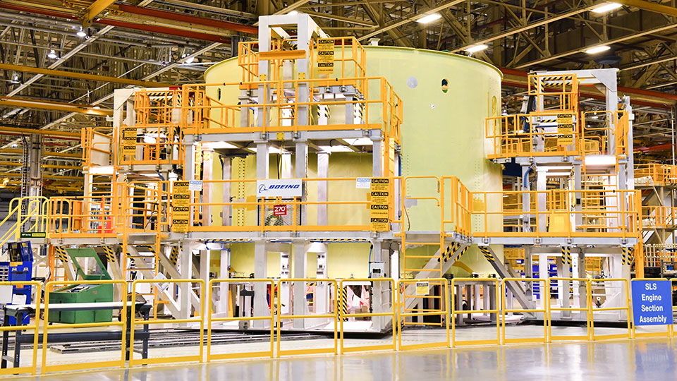
Regarding the Core Stage engine section, according to Boeing’s Space Launch System Vice-President and Program Manager John Shannon, it was the longest pole in the tent for completing the Artemis 1 Core Stage. If you ever see pictures of the Shuttle’s engine section, it looks crowded with the hardware needed for the engines including avionics, brackets, wires, and tubing. Before any of the avionics, hardware, plumbing, tubing, wiring, and other parts of the SLS Core Stage engine section are installed, the engine section looks roomy inside, which is deceptive. According to Shannon, only about 10 people can work efficiently inside the engine section. For CS-1, that meant slow work on the most complicated part of the Core Stage. One change Boeing made in building the engine section going forward is how Core Stage engine section subsystems are built. Originally, subsystems were to be built inside the engine section. A big change Boeing has made is to build those engine section subsystems outside the engine section and then drop them into the engine section. According to Shannon, this can mean 50 people, not just 10, can be making progress on building the SLS Core Stage engine section.
During the course of building the Core Stage 1, Boeing workers at Michoud made, and continue to make, recommendations that will see improvements in build-time of future core stages. According to Boeing, the Artemis 2 Core Stage will be built in 40% of the time it took to build the Artemis 1 Core Stage. Before the Artemis 1 Core Stage was installed on NASA’s Pegasus barge, it underwent a suite of functional testing including fittings and pressure tests, and passed with flying colors. This serves as a testament to the quality and thoroughness of the work done by the Boeing workers at Michoud.
At this time, the Core Stage 1 is being secured inside Pegasus and hooked-up to purging systems. Once that is completed, and weather permitting, Pegasus will begin the 9 hour trip to Stennis Space Center. Once at Stennis, the Core Stage 1 will be unloaded and installed on the B-2 Test Facility for the stage’s Green Run, a process made more efficient, according to NASA’s SLS Program Manager John Honeycutt, because of the lessons learned in working with the SLS Core Stage Pathfinder.
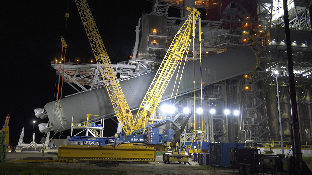
The Green Run will occur over several months. Initially, testing will involve activating and monitoring individual subsystems of the Core Stage 1. Once the individual subsystems testing is completed, the penultimate test for the Core Stage 1 will be done, the wet rehearsal. During the wet-rehearsal, cryogenic liquid oxygen and hydrogen will be loaded into the LOX and LH2 tanks. This will be the first time that’s the Core Stage and its hardware, avionics, software, wiring, tubing, and plumbing will be exposed to cryogenic conditions.
Because of experience during cryogenic testing during the Shuttle program, Boeing has arranged for its SLS team to be available for trouble-shooting should issues arise from the cryogenic testing. Once the liquid oxygen and hydrogen tanks are drained, modifications and repairs caused by the thermal contraction and expansion that occurs under cryogenic conditions will be made to the Core Stage 1.
If all goes well in the cryogenic testing, a week later the tanks will be loaded once again with liquid oxygen and hydrogen and individual test firings of the four RS-25 engines will be conducted. This will also begin the modal testing of the SLS Core Stage 1.
The culmination of the Green Run test will be the firing of all four RS-25 engines for the full-duration, full throttle range of a launch, up to 111%, which is an improvement to the Space Shuttle’s 109%. One goal of the Green Run test is to demonstrate that the liquid hydrogen bleed-off that the SLS Core Stage uses to power the avionics and pressurize of the liquid hydrogen tank operates as designed when all four RS-25 engines are gimbaled to their maximum limits.
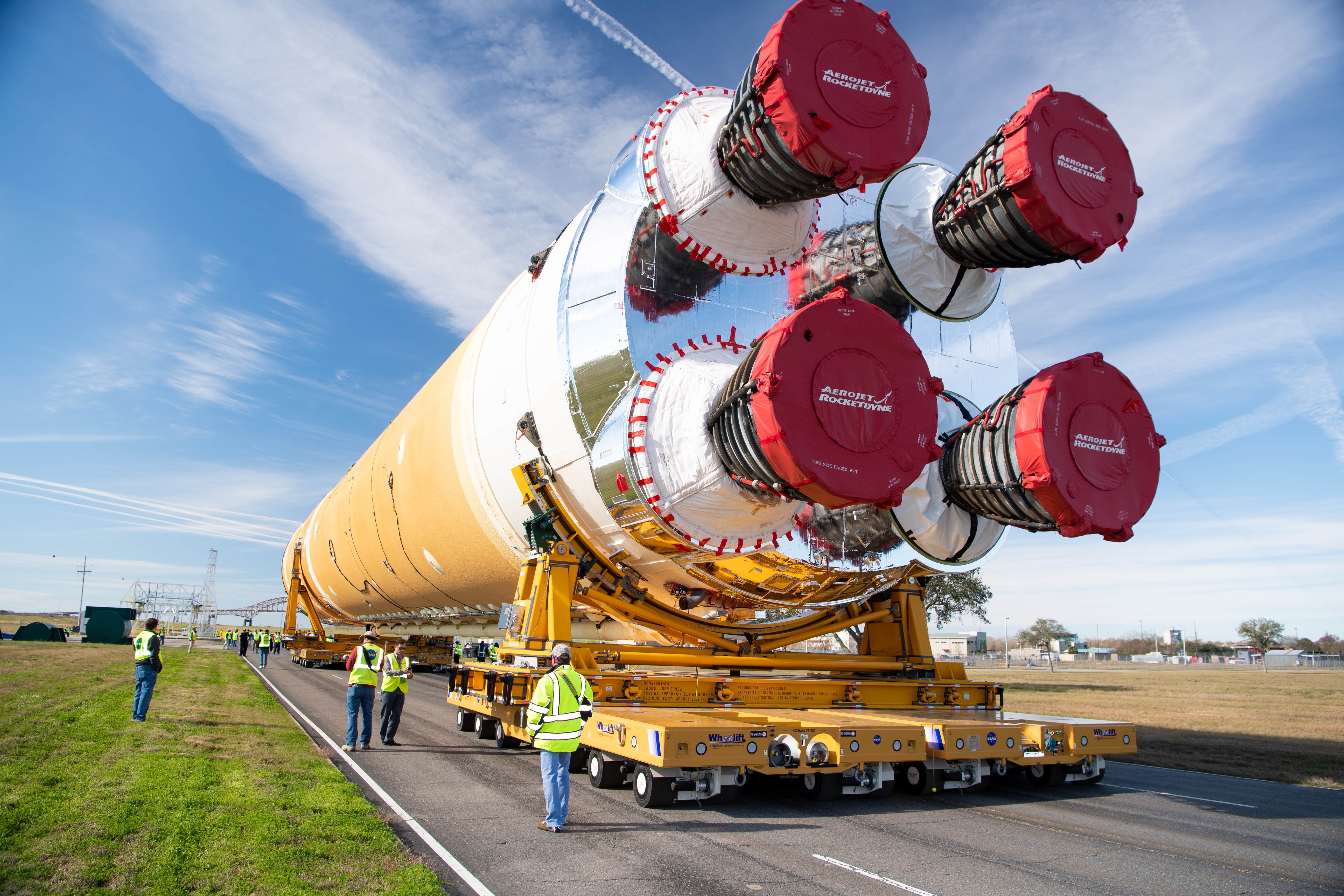
Boeing has tried to prepare the Core Stage 1 to handle the conditions of the hot-fire test. One change made to the Core Stage 1 was the application of a thermal coating on the Engine section’s boat-tail. The boat-tail’s thermal protection system employs a thin cork material. During a hot-fire, testing showed that the cork material would char, just as it would during a launch, meaning that it would need to be replaced before launch of Artemis 1. Analysis by Boeing showed that the application of the silvery thermal coating on the cork insulation would prevent charring, meaning that, hopefully, it doesn’t need to be replaced after the Green Run in completed. After the full-duration hot-fire test of the Core Stage 1, it will be refurbished and repaired as needed, and prepared for its 8-12 day trip aboard the Pegasus bard to Kennedy Space Center. The time-span for concluding the Green Run is between July and October.
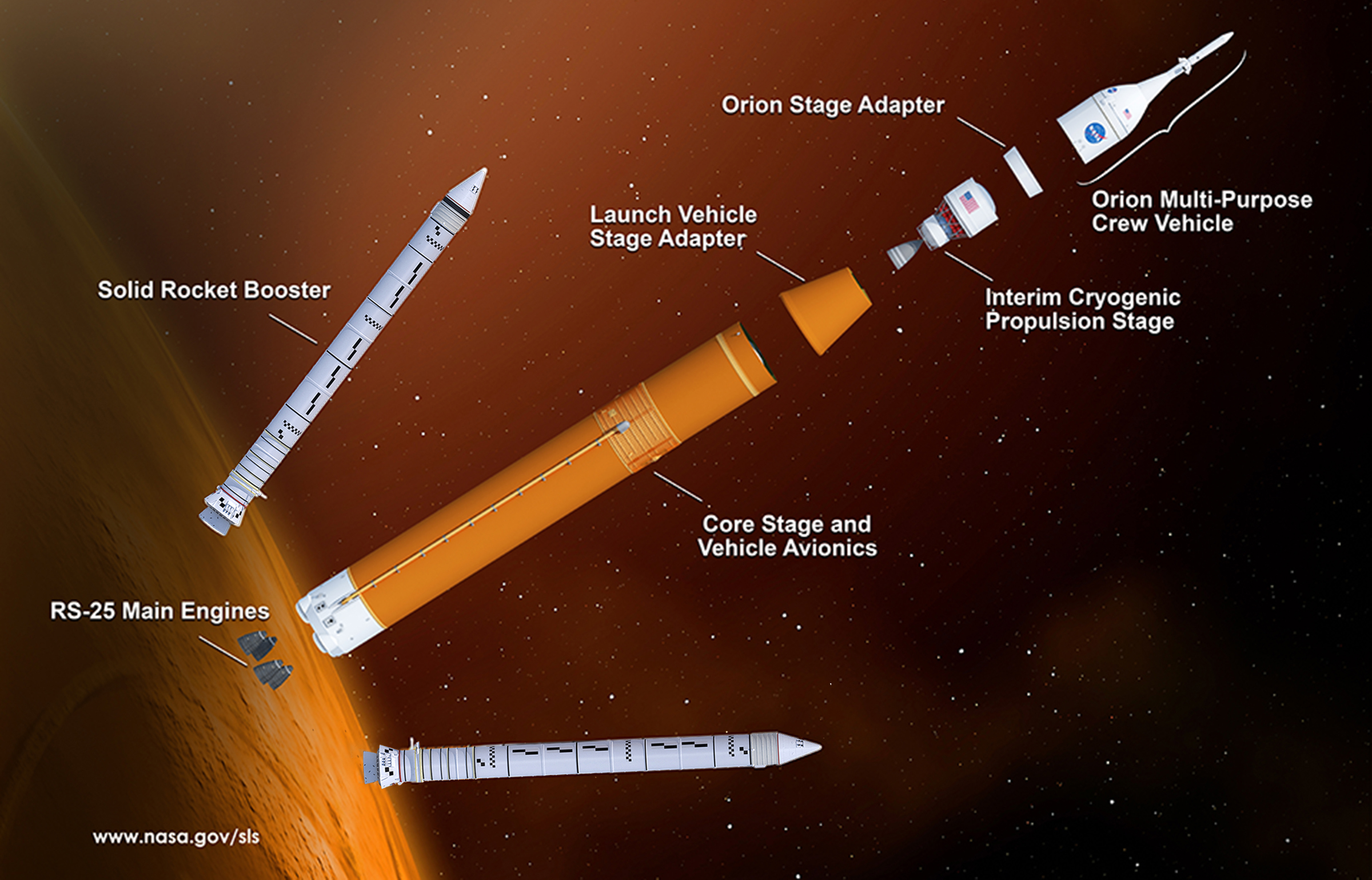
Once at Kennedy Space Center, NASA’s SLS program will turn-over the Artemis 1 Core Stage to NASA’s Exploration Ground Systems, or EGS. It is EGS that will do final preparations of the Core Stage 1 in the Vehicle Assembly Building, or VAB. Once the Core Stage 1 is ready, it will be hung on the already-stacked SLS solid rocket boosters. The next step in stacking the Artemis 1 rocket will be to install the launch vehicle stage adapter (LSVA). Then the [Interim Cryogenic Propulsion Stage (ICPS)](https://www.nasa.gov/exploration/system s/sls/interim-cryogenic-propulsion-stage-infographic-for-sls.html) and its Orion Stage Adapter (OSA) are stacked. Inside the Orion Stage Adapter are 13 mounting spaces for small satellites that will get a push needed to explore deep space. Completing the stack will be the Orion spacecraft, with its crew module (CM) and service module (SM), and the Launch Abort System (LAS).
.
.
FOLLOW AmericaSpace on Facebook and Twitter!
.
.




WE ARE GO!!!!!
Such great news!
–publiusr