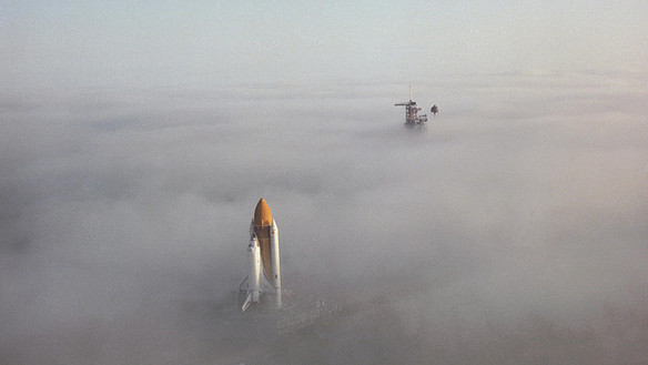
Thirty years ago this week, America’s second space shuttle thundered into orbit for the first time. Challenger spent five days circling the Home Planet, deployed a giant communications and data-relay satellite for NASA, and saw the first U.S. spacewalk in nearly a decade. The story of Challenger is naturally overshadowed by the dreadful tragedy which befell her in January 1986, but for several years she was the most-flown orbiter in NASA’s shuttle fleet and accomplished several significant feats in rendezvous, retrieval, repair, spacewalking, and as a satellite launcher. Yet perhaps Challenger’s most remarkable achievement is that she might never have existed at all and, but for a quirk of fate and timing, might have begun and ended her days as a non-descript structural test article.
In April 1981, Columbia became the first shuttle to travel into orbit, and it had long been hoped that her predecessor, Enterprise, would be upgraded to make her spaceworthy. Enterprise had flown a series of captive and free flights over the California desert in the summer of 1977, and lessons learned during her assembly had been incorporated into the design of Columbia. However, it was recognized that Enterprise weighed too much to carry a payload into orbit. She would need a new set of plans to make her capable of flying in space. Moreover, she had no propulsion systems, plumbing, fuel lines, or propellant tanks. Her main engines were dummies, her payload bay had no attachments for cargo, its doors had no opening mechanism or radiators, and her thermal protection system was little more than polyurethane and fiberglass. Inside her cabin, she had no star trackers or heads-up displays, no aft flight deck or overhead windows, no airlock, no middeck lockers, no galley, no cryogenic fuel cells, and her landing gear was operated by explosive bolts. In short, modifying Enterprise for space would be a long, hard road to tread.
Enter Structural Test Article-99.
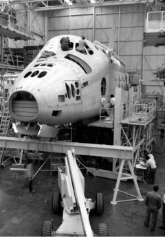
Since the original contracts for the shuttle were signed in July 1972, virtually all components were tested to handle significant stress. Limited computing power meant that it was difficult to predict mechanical and thermal loads, and NASA built STA-99 as an engineering tool. After its completion in February 1978, it was tested for a year in a steel rig at Lockheed’s Plant 42 in Palmdale, Calif., where conditions of launch, ascent, orbital flight, re-entry, and landing were simulated. The decision to modify STA-99 as a “real” orbiter came about because, unlike Enterprise, it was an incomplete airframe and could be more easily upgraded. Traditionally, manned spacecraft had been tested to 140 percent of their design strength, but NASA engineers recognized that this might cause so much damage to STA-99 as to make it inadvisable to do so. Consequently, Tom Moser and his team at the Johnson Space Center in Houston, Texas, developed an analytical computer model to simulate 3,000 measurement points on the airframe. Their results confirmed that it could easily withstand 140 percent loads, with actual stress distributions in critical areas comparing favorably with pre-test data.
On 29 January 1979, it was official. Under a $1.9 billion contract between NASA and Rockwell International, STA-99 would follow Columbia as the second orbiter. Four days later, on 2 February, the structural test article was renamed “Challenger,” in honor of a steam-assisted Royal Navy corvette, which undertook a prolonged cruise from December 1872 until May 1876. In support of this expedition, all but two of Challenger’s guns were removed and her spars reduced to increase the availability of space for laboratories, additional cabins, and a special dredging platform. Equipped with specimen jars, alcohol to preserve samples, microscopes and chemical apparatus, thermometers, sounding leads, and sediment collectors, the 80,000-mile Challenger Expedition gathered the equivalent of 50 volumes of information about the Atlantic and Pacific Oceans. Sadly, she was broken up for her copper bottom in 1921 and, today, nothing, save her figurehead remains; this is enshrined in the National Oceanography Centre in Southampton, England.
For the orbiter Challenger, ground evaluations, practice landings, and structural test articles were no substitute for actually operating in space. Before she could be declared ready for flight, Challenger required substantial disassembly and rework at Rockwell International’s Palmdale plant in November 1979. Her payload bay doors, aft body flap, and elevons were removed and returned to their vendors for refurbishment, followed by her vertical stabilizer in January 1980. She had been built with a simulated crew cabin, which required the two halves of her forward fuselage to be opened to remove it for modifications. In July 1981, after its own series of improvements, the aft fuselage returned to Palmdale. In physical appearance, the rebuilt Challenger looked similar to Columbia. External appearances, though, proved deceptive. “Challenger would end up some 2,889 lb lighter,” wrote Dennis Jenkins, “in spite of having additional operational equipment installed and the more robust structure.” This saving was also achieved through the absence of ejection seats, the replacement of several hundred thermal protection tiles with new insulating blankets, the removal of a number of tube-supporting frames, the use of lightweight “honeycomb” for her landing gear doors and vertical stabilizer, and the incorporation of less weighty main engine heat shields.
By December 1982, most of the preparations in support of Challenger’s maiden voyage, STS-6, had already been completed; in fact, attached to her External Tank and boosters and partially enshrouded in a gloomy midwinter fog, she crept out to Pad 39A on 30 November. Once there, a critical exercise lay ahead: the Wet Countdown Demonstration Test, which was scheduled to culminate on 18 December in a 15-second firing of her three main engines. This Flight Readiness Firing (FRF) was needed to demonstrate the engines’ ability to throttle and gimbal under hydraulic command, just as they would be required to do during launch. Preparations for the FRF proceeded in a manner not dissimilar to a real countdown.
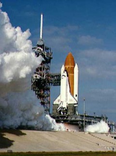
With a minute to go before engine ignition, the NASA commentator picked up the coverage: “T-1 minute and counting … the firing system that releases the sound suppression water onto the pad has been armed … T-50 seconds and counting … T-45 seconds and counting … T-40 seconds and counting; SRB development flight recorders are being turned on … T-37 … gaseous oxygen vent arm will not be retracted on this particular test … T-31 seconds, we have a Go from LPS [Launch Processing System] for auto-sequence start … [Challenger’s] four primary flight computers taking over control of the terminal count … final LPS command for engine start will occur at approximately ten seconds … T-15 seconds and counting … ”
At this stage, the relative silence and serenity on the pad changed markedly. First, the sound suppression water began to gush across the launch pad from four gigantic “rainbirds.” “T-10 … Go for main engine start … we have main engine start … ” All at once, a sheet of orange flame gave way to a trio of shock diamonds from the three main engines, combined with a thunderous roar and vast cloud of smoke. The engines ignited in a ripple-like sequence, starting up at 120-millisecond intervals, reaching 90 percent of rated performance within three seconds and hitting the 100-percent mark precisely as the countdown clock touched zero: “T-0, engines throttled at 100 percent, all engines up and burning … T+5 seconds, engines continuing to burn … T+10 seconds … twelve … first [engine] cutoff at T+15 seconds … [Number One] engine cutoff … and engines Two and Three also cutoff at 16.8 seconds … T+25 seconds; GLS [Ground Launch Sequencer] safing now in progress … ”
Challenger’s main engines were capable of achieving 104 percent thrust—a 4 percent increase over Columbia—which enabled her to transport heavier payloads aloft. In fact, for each one-percent of performance increase over rated thrust, the new shuttle gained 990 pounds of additional payload-to-orbit capability. Challenger’s higher thrust was accomplished by incorporating redesigned components into each engine. Such changes became necessary in anticipation of higher temperatures, pressures, and pump speeds that they would encounter at the greater thrust levels. A series of test firings, lasting over 62,000 seconds, had been performed to validate the engines in readiness for their first orbital mission; additionally, the main injectors employed stronger liquid oxygen posts and modified fuel pre-burners to overcome turbine blade erosion and thicker tubes and coolant supply lines to handle higher aerodynamic loads at liftoff.
However, their performance during the FRF was not entirely successful.
As they blazed at full power on 18 December 1982, engineers detected levels of gaseous hydrogen in Challenger’s aft compartment which significantly exceeded allowable limits. When it became impossible to pinpoint the cause or location of a leak, the decision was taken to perform a second FRF. New instrumentation was installed both inside and outside the aft compartment to determine whether the hydrogen was leaking from an internal or external source. Suspicion focused initially on the latter possibility, because vibration and current had found their way into the aft compartment, behind the engines’ heat shields. By the beginning of 1983, launch was not anticipated before 1 February, at the earliest. However, the second test firing on 25 January, during which the engines were run at 100 percent for 23 seconds, again revealed the presence of leaking hydrogen gas.
Several more days of troubleshooting eventually identified a cracked weld in tubing leading to the uppermost (Number One) engine, which was promptly removed on 4 February. A replacement was delivered, but initial inspections in the VAB uncovered a leak in an inlet line to its liquid oxygen heat exchanger. Before it could even be installed onto Challenger, the “replacement” was itself replaced by a third engine. After more checks, including a 500-second, full-flight-duration test firing, it was dispatched from Mississippi to Florida on 3 March and fitted a week later.
Unfortunately, while this work was ongoing, painstaking efforts were underway to ensure that the other two original engines did not exhibit any leaks—and the bad news seemed to be that they did! Towards the end of February, hairline cracks were found in one of the fuel lines to the left-hand (Number Two) engine, and borescope observations of the right-hand (Number Three) engine revealed a similar problem. Both were removed, returned to the VAB and repairs were conducted. With the arrival of the replacement engine from Mississippi, all three were installed by mid-March and verified as being ready to support a launch. The leaks from the Number Two and Three engines were apparently caused by a generic “seepage” in an inconel-625 tube situated in their ignition systems. It apparently occurred underneath a protective sleeve brazed onto a small hydrogen line which sent fuel to the engine’s augmented spark igniter. The sleeve was designed to counter possible chafing. After practicing cutting off the sleeve on the Mississippi plant’s test stand, Rocketdyne technicians replaced it with a non-sleeved inconel-625 tube on each of Challenger’s engines.
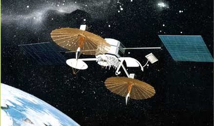
By the time their orbiter was finally declared “flight ready,” the four-man crew of STS-6 had already performed their Terminal Countdown Demonstration Test, and, on 5 February, the payload for their five-day mission—the first in a series of large Tracking and Data Relay Satellites (TDRS), attached to an Inertial Upper Stage (IUS) booster—was transferred to the launch pad and inserted into the payload bay. The impressive TDRS/IUS combo filled three-quarters of the bay and was by far the largest payload carried by the shuttle. After deployment, ten hours into the mission, the two-stage, solid-fueled IUS would boost the TDRS into a geostationary transfer orbit and finally circularize that orbit at 22,000 miles above Earth. Before launch, the satellite was alphabetically designated “TDRS-A,” but when fully operational it would be numerically renamed “TDRS-1.”
In spite of the engine leaks, the payload had originally been moved to the pad a couple of days after Christmas, but when it became clear that Challenger would not be flying in January 1983 and another FRF would be needed, it was returned to the Vertical Processing Facility for temporary storage. By the end of the first week in February, it was back at Pad 39A and ensconced in the Payload Changeout Room of the Rotating Service Structure for installation aboard the shuttle. Then, on 28 February, strong winds whipped across the launch area and breached a weather seal between the changeout room and Challenger’s payload bay, depositing a fine layer of particulate material on the satellite’s solar array deployment springs. This resulted in an additional delay from 26 March until 4 April.
After thorough inspections, TDRS-A was removed and carefully cleaned, before being replaced aboard the shuttle on 19 March. The plan was to follow up with the second TDRS in the summer of 1983. They would provide near-continuous voice and data relay traffic between Mission Control and future shuttle crews, as well as support an ambitious series of future scientific missions, including the Hubble Space Telescope. Unfortunately, a long and difficult road would have to be travelled before TDRS-A could enter operational service.
The second part of this article will appear tomorrow.



2 Comments
2 Pings & Trackbacks
Pingback:30 Years Since STS-6: The Mission of the ‘Geritol Bunch’ (Part 2) « AmericaSpace
Pingback:30 Years Ago: First Shuttle Night Launch, First African-American Astronaut, Oldest Man in Space (Part 1) « AmericaSpace