A look into the research and development, mission objectives, and people behind our latest Earth science observatory, NASA/JPL’s Soil Moisture Active Passive, SMAP.
Flying out of Vandenberg Air Force Base in the pre-dawn morning of Jan. 31, 2015, a unique Earth science mission from NASA’s JPL began a three-year-plus mission to map Earth’s changing soil moisture and its freeze/thaw state.
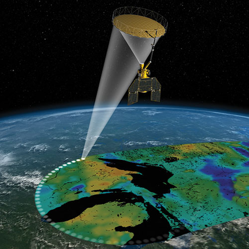
Through cloud cover and vegetation, the new observatory, SMAP, will record the moisture content of our planet’s soil every two to three days. Even the moisture content of crops growing in the fields may be measured to ensure an abundant harvest. Once SMAP has completed its calibration and verification study, it’ll become one of the most effective instruments ever created to observe the metabolic rate of our planet.
Near Vandenberg on the California coast, a mountain range of ancient shale and gray-green sandstone called the Santa Ynez cuts its way west through rolling meadows in a line to the sea. It’s a curious point where the two meet. The Chumash People believe it to be sacred, a kind of stepping off point for souls to begin their celestial journey. Known as Point Conception, it also marks the boundary between Central California and the lower third of the state.
Just south of the point, where the rock wall striations of the Santa Ynez thrust into the waters of the Pacific, the land falls away in a decisive retreat from the sea like a massive tidal pool filling. The coastline juts inland, hard to the east, then curves back in a southerly crescent as far as Ensenada, Mexico. Oceanographers call this region the Southern California Bight.
During the winter months, powerful ground swells come rolling in deep from the waters of the Pacific, forming point break surf, waves that travel for some distance, holding their shape as they meet the contour of the shore.
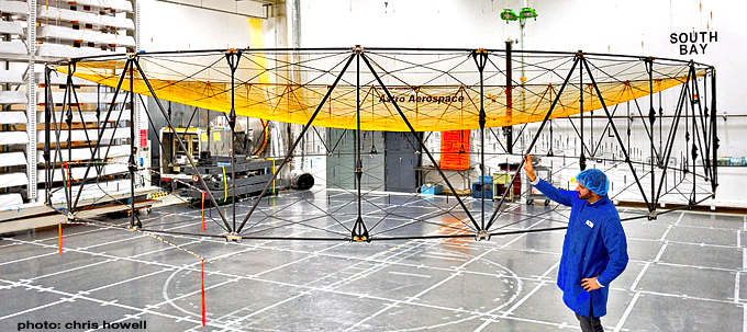
Along this stretch of coast, a group of visionary engineers with a bent for telemetry set up shop in 1958 and called their outfit Astro Aerospace. They make spacecraft; or more accurately, they make antennas for spacecraft—big ones—parabolic reflectors more than 12 meters in diameter. They also made the 6-meter spinning reflector and boom for SMAP, the largest spinning array ever attempted on orbit.
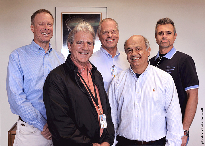
In part two of our story, The Eyes of SMAP, we met with Astro Aerospace General Manager John Alvarez and engineers Dan Ochoa and Ryan Meschewski, members of the development team responsible for SMAP’s 6-meter spinning parabolic antenna.
- Q: With SMAP’s 6-meter reflector successfully deployed and spinning at more than 14 rpm, how would you characterize the mission to date?
A: It’s great! Everything is going as we’d planned, totally nominal. The data looks very good. All of the downloads and analysis at JPL couldn’t be much better. Everything points to a complete success.
- Q: I understand the boom and reflector opened right on cue. How were you able to confirm that the deployment was nominal, that the geometry of the reflector is consistent and evenly tensioned?
A: We believe the geometry looks very good. We correlated that just after the reflector deployed by doing a frequency check of a fully deployed reflector. We did an analysis and found that it matches up very closely to what is actually seen on the spacecraft.
- Q: I’ve heard the reflector described as being origami-like in its transformation as it opens. Is that a metaphor used during project development, creating a form that folds, then opens expressively, resembling the sculptural art of paper folding?
A: Determining how to make structural components that need to be large in orbit, yet compress into a tight package for launch is a strength of our company. It’s what we’ve been doing since we began in the 1950s at the start of the space race. Our deployable antenna systems and structural elements such as telescoping masts, booms and trusses continue to function on spacecraft orbiting the Earth, the Moon, and Mars, on the surface of Mars and now, traveling beyond our Solar System.
The deployable structures we created for the Voyager program enable both spacecraft to measure the effects of solar winds and magnetic fields as they journey through the heliosphere of our Solar System, and now, as they move beyond into interstellar space more than 35 years after launch.
This is what we do, equipping difficult missions with deployable structures and mechanisms that make it possible for spacecraft to perform their mission objectives. We’re proud to say that in our company history of more than 50 years, we hold a 100 percent success rate in mission deployment for all of the components we’ve designed and built. The origami metaphor is fitting—a good description of something that folds very elegantly.
- Q: When you begin a project like this, where do you start? Do you begin with a CAD program on the computer? Do you sketch it out on napkins? Where does it all begin?
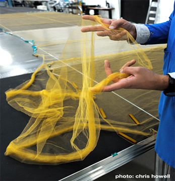
A: We developed a product called AstroMesh, our name for the large deployable parabolic antennas we produce. AstroMesh uses a gold-plated molybdenum knitted mesh as a reflector surface for RF (radio frequency). The perimeter truss and reflector surfaces are designed to collapse, or furl, into a small diameter for launch, then deploy to full dimension when the spacecraft reaches its objective.
Our clients choose the AstroMesh reflector because they get a very large, high performance parabolic antenna that is extremely lightweight and with proven dependability. Both are critically important for a structure so large in relation to the spacecraft.
With SMAP, we had to develop a 6-meter reflector that would furl into a package 12 inches in diameter, weigh less than 60 lbs and be certain that it would perfectly deploy. The boom was also a major consideration. It needed to extend the reflector 11 feet off the spin deck of the spacecraft at a 40-degree angle and be stiff enough to hold the antenna in perfect alignment without any distortion when spun up to its science objective of just under 15 rpm.
Because of these constraints, and the need to reduce the weight of the reflector even further, we went with AstroMesh Lite for SMAP’s reflector. It’s the lightest and most compact version of our mesh reflector product line. The lighter material is designed for apertures in the 3 to 8-meter diameter range. SMAP is the tenth AstroMesh deployable reflector to launch with every single one performing flawlessly on orbit. Deploying systems like solar panels and antennas in orbit is one of the riskiest parts of the mission. You only get one shot at it, so it has to work perfectly the first time.
- Q: I’ve heard that the 6-meter dish on SMAP is the largest rotating reflector operating in space today.
A: It’s by far the largest rotating reflector, as well as the largest mass balanced reflector. It’s also the first mesh reflector successfully deployed in space to be used to collect science data, as opposed to RF communications.
- Q: How were you able to balance the mass of a unit that large, spinning at over 14 rpm with its boom offset at 40-degrees?
A: We provided very accurate mass data-moments of inertia, center of gravity specifications and the like to JPL so they’d know the precise characteristics of this reflector. We modeled and weighted each one of our 15,000 individual parts as we were building it, then again in different phases of assembly and through to the final assembly.
The mass properties measurements that we needed were so unprecedented we had to invent some of the methods used acquire them. For certain tests we brought in machines typically used to balance airplane engine blades. These machines were so sensitive that breathing near the equipment during measurements was found to skew the results. This level of accuracy was imperative because the reflector, designed to function in the microgravity of space, could never be spun-up in the 1 g of Earth, so we had to be absolutely certain before launch.
- Q: How did you compensate for any distortion the force of the spin might put on the structure?
A: The reflector is well characterized by its mass. We had to keep the mass within a 3.5-ounce window (the weight of about 39 pennies) and the center of mass within a ½ inch window. The reflector is attached to the spacecraft through our 11-foot boom. We built the reflector and boom knowing that the spinning shape would differ from the original shape. It’s similar to a washing machine, after the spin cycle all of the clothes are stuck to the sides. Our reflector is no different; the tip moved over 2 inches from its pre-spinning to spinning shape, so we had to make sure that it changed in a controlled manner. To accomplish this, we attached specific masses, or, counterbalances, on the reflector where they were necessary.
- Q: Something like balancing a wheel on a car?
A: Yes, somewhat. But imagine that the wheel weighs 125 lbs, is 20 feet in diameter, and only starts to spin after it’s in space.
We had very strict guidelines on where our array would point, that is, where it would reflect the signals given to it by the spacecraft. The pointing requirements were measured in millidegrees. To put this in perspective, 1 millidegree rotation of our assembly translates to an offset of about the thickness of a hair at the reflector tip. By the time we were ready for launch, the term “splitting hairs” had taken a whole new meaning.
- Q: Sounds like the spin presented the biggest obstacle.
A: Yes. The spin was our biggest challenge. We knew our success would depend on how accurately we’d be able to measure the mass, the center of gravity, predict the moments of inertia, and so on.
We worked closely with JPL throughout the project, providing them with models of the mass balancing of this large antenna. It took a lot of effort and was a significant challenge to accomplish.
- Q: So, the name AstroMesh Lite refers not only to the reflective surface, but to the entire structure as well?
A: Yes. The mass of the entire structure is lighter than the mass of previous larger reflectors that we’ve flown.
Relative to other units we’ve built, this is a smaller reflector size. We designed the AM Lite for an aperture range of 3-8 meters. So this particular reflector falls right within that range. AM 1 is our designation for our larger reflectors. They go from 8 meters up to 20 or more.
- Q: These are fixed, non-spinning antennas?
A: Correct, they don’t spin. So far, all of our larger reflectors are used as parabolic antennas on communication satellite systems, usually in a geosynchronous (GEO) orbit covering one large spot on Earth with a constant communication stream, so they don’t need to spin like SMAP. The spin of the reflector on SMAP enables the spacecraft, which is in low-Earth orbit (LEO), to scan the entire globe in two to three days.
- Q: How are you able to form that parabola? In all the photographs and illustrations I’ve seen of the extended reflector, I haven’t been able to make out how the material is held in the shape of the dish. How were you able to achieve that?
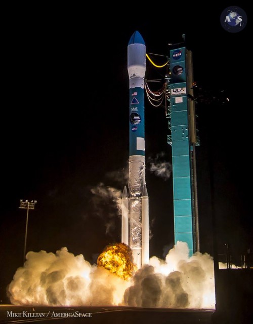
With the flare of its RS-27A first-stage engine and trio of Solid Rocket Motors (SRMs), the Delta II takes flight with SMAP at 6:22 a.m. PST Saturday, 31 January. Photo Credit: Mike Killian / AmericaSpace

A: That’s a very good question. It’s the way we build these reflectors, and a big part of why they work so well. The parabolic surface on the reflector is actually a geodesic structure of gold molybdenum knitted mesh and Kevlar fiber web. We approximate a perfect parabolic surface with facets. The facets are made up of an intricate web of Kevlar fibers. The Kevlar fiber webs are attached to the perimeter truss structure, which is a jointed circular truss made out of graphite tubes and bonded joints. When the truss structure is fully deployed, it pulls the mesh and Kevlar fiber webs into tension. It’s like a drum or a high performance tennis racket. There are actually two surfaces there. There is a mesh and web on the front, reflecting surface, but on the backside surface you don’t see a mesh, but rather the same Kevlar fiber web pattern that is on the front. Now, in between the web on the top surface and the bottom surface we have tension ties.
The tension ties are designed and sized to pull the front mesh surface into the correct parabolic shape once the perimeter truss is deployed. This design allows for us to very accurately create a stiff and nearly perfect RF reflective parabolic surface out of very flexible materials. Flexibility is of course important because this whole system of mesh and Kevlar fiber webs needs to be stored in a compact bundle when the reflector is stowed for launch before it deploys on orbit. It really is an amazing design.
- Q: It brings to mind my college days at Antioch when a radical design group called Ant Farm showed up with a radio frequency welder and huge rolls of Visqueen plastic. We’d design shapes, do the math, determine the gore factors, cut the material, weld it all together with RF, and inflate them with fans.
A: Exactly. A lot of analysis goes into sizing the components that make up the surface facets, like the gores patterns in the inflatables you described. We have some proprietary analytical tools and design methods which allow us to create a parabolic reflector with a very specific antenna prescription.
- Q: Do other applications come to mind for this unique 1000-kilometer swath, spinning reflector technology in addition to SMAP’s soil moisture mapping?
A: If you think of the Direct TV dish you have on your house, we make the antenna dish that’s in geosynchronous orbit communicating with the dish on your home. So, our reflectors are used primarily for communications. This is the first large deployable reflector we’ve done for a science mission and we’re very excited about that. We’re sure there are many other missions that would benefit from the technology developed for SMAP. Any spacecraft in low-Earth orbit with a mission to map the globe every two to three days could use this spinning technology. We broke new ground on this, and hope to find for more applications for it.
- Q: I’m sure they’ll show up. Is there anything else you might want to share having to do with challenges faced on this new project, developing this system?
A: The boom we designed and built for SMAP also plays an integral part in the success of the mission. Designing a lightweight structure with very stiff properties is something we pride ourselves in. In this case, the boom had to be stiffer, more robust than normal because of the forces induced by the spin. Holding the reflector in a known position with stable characteristics is critical to the performance of the spacecraft. If the angle of the reflector were off by only one or two degrees, the beam projected onto the surface of the Earth would be askew.
We determined that the dynamic loading on the structure once the spin was dialed up to operational speed would affect the angle of the beam. So, our solution was to design the boom to deflect just enough to align the reflector when the spin reached 14 rpm. We did a lot of analytical work on the ground to confirm this, measuring the actual flight hardware with high-resolution photogrammetry, and it paid off!
When SMAP spun up to operational speed, the boom and reflector flared into their intended angle just as we’d planned! The team at JPL continues to monitor the antenna in full spin mode and reports the system alignment is about as close to perfect as it can get. We’re ecstatic! The team’s commitment, hard work, and planning have come through again. We love what we do.
- Q: Now that SMAP is fully functional and undergoing its calibration and verification phase, what’s next?
A: We’re excited about a number of projects in our shop right now including the James Webb Space Telescope and Starshade, a mission from NASA/JPL, still in its preliminary stages, to identify Earth-like planets in other star systems.
Special thanks to JPL’s Alan Buis, Kent Kellogg, Simon Yueh, and Wendy Edelstein.
Want to keep up-to-date with all things space? Be sure to “Like” AmericaSpace on Facebook and follow us on Twitter: @AmericaSpace
Missions » SMAP »
I did not know Delta could fly with 3 SRMs.