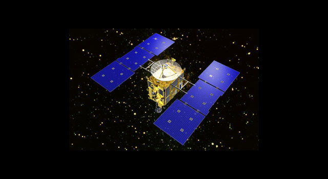
Image Credit: JAXA
Nippon Telegraph and Telephone Corporation (NTT, CEO: Hiroo Unoura, Tokyo) and Japan Aerospace Exploration Agency (JAXA, President: Naoki Okumura) have achieved the world’s first microwave electric-field measurement with the newly developed optical electric-field sensor based on an optical fiber (fiber-optic EO probe*1) in plasma inside a microwave discharge ion engine*2 for use on asteroid explorers etc. This achievement contributed to the investigation of the plasma production mechanism in the microwave discharge ion engine during actual operation, which has been difficult thus far. This investigation will make it possible to design the ion engine with higher performance characteristics, and thus, it is expected to allow the deployment of more effective and efficient space activities, enabling future asteroid explorers with an improved ion engine to set out for even more distant asteroid and with a prolonged lifetime.
1. Background Electric-field sensors conventionally comprising metal components are widely used to measure various kinds of electromagnetic wave such as weak ones fount in nature and artificially generated high-power microwaves. Since conventional electric-field sensor can disturb radiated electromagnetic waves, it is an inherent issue when attempting to precisely measure the desired electric field. To overcome this issue, NTT has developed an EO probe employing an optical fiber which is generally used as a main tool in optical communications (Fig. 1). Moreover, JAXA has been promoting the research and development of the ion engine boarded on the asteroid explorers and achieving improvements in its propulsion performance. To develop an improvement mechanism, JAXA required the ability to measure the microwave electric-field distribution of the internal plasma in the ion engine during actual operation. However, since conventional electric-field sensors can provide disturbances such as scattering the electric field and require undesired modifications to the ion engine for insertion, it is difficult to precisely diagnosis internal phenomena based on microwave electric-field measurement of the accelerated plasma in the ion engine during operation. Thus, from the viewpoint of non-invasiveness and the high spatial resolution of the fiber-optic EO probe which has been developed by NTT based on an optical fiber, the research and development of microwave electric-field measurements in the ion engine have progressed under the collaboration of NTT and JAXA (Fig. 2).
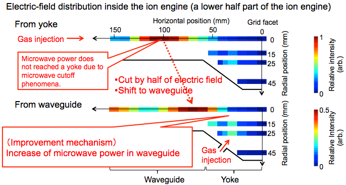
2. Achievements NTT and JAXA have successfully improved the sensitivity stability as well as thermal and magnetic resistances to satisfy the requirements of the fiber-optic EO probe (Fig. 3 and 4), and achieved the world’s first microwave electric-field measurement in the ion engine (Fig. 5). From these results, an improvement of the ion engine via reduction of the microwave cutoff phenomena*3 (Fig. 5) has been revealed. Hereafter, more research and development of the microwave discharge ion engine will be conducted and thus it is expected to enable the deployment of more effective and efficient space activities, for instance, future asteroid explorers with an improved ion engine will set out for even more distant asteroids and their lifetime will be prolonged.
3. Technical Features These results were achieved by the combination of NTT’s technological advancement of the fiber-optic EO probe and JAXA’s sophisticated techniques for microwave electric-field measurement in the ion engine.
(1) Improvement of performances in the fiber-optic EO probe (Fig. 3 and 4)
- For stable measurements with fluctuation less than that of microwave generator output, the use of a low coherence optical source suppressed the optical resonant phenomena in the optical fiber. Accordingly, the sensitivity fluctuations of the fiber-optic EO probe have been reduced from 16% to under 10%
- For application of the fiber-optic EO probe to high magnetic-field areas in the ion engine, the redesign of the optical components weak against high magnetic fields has improved the magnetic-field resistance. As a result, the magnetic field resistance was increased from 0.1T to over 0.8T.
- For application of the fiber-optic EO probe to high temperature areas, the water cooling system with a double capillary structure was introduced. The outer diameter of the double capillary structure is 3 mm, allowing insertion to the inside of the ion engine through an acceleration grid without perforating any additional holes.
(2) Electric-field distribution measurements in microwave discharge ion engine (Fig. 5)
Precise microwave electric-field measurements in the ion engine were demonstrated in the plasma source under beam acceleration during its actual operation.
4. Future Plans In this developed fiber-optic EO probe, we are considering the issue of the operability of optical components due to their complicated design structure and the long-term reliability of optical adhesive resin which is used to fix the optical components such as an EO crystal and the optical fibers. NTT will aim to improve the operability by applying a novel structure of the fiber-optic EO probe and increase the reliability by the improvement of the optical adhesive resin. The last step will be to finalize the design of the fiber-optic EO probe for obtaining microwave electric-field measurement within the microwave discharge ion engine. JAXA will aim to diagnosis various internal phenomena in the microwave discharge ion engine and thus to further improve its performance in order to deploy more effective and efficient space activities. The end goal of this project is to develop an ion engine capable of reaching more distant asteroids than ever before and provide a prolonged operational lifetime.
[Footnote] *1 EO probe Pockels effect is a linear electrooptic (EO) effect where the relative index changes linearly with the electric field applied to a crystal. NTT’s developed EO probe is based on the Pockels effect and is mounted on the tip of the optical fiber. Thus, the EO probe is superior to other probes in its flexibility.
*2 Ion engine An ion engine is a form of electric propulsion used on spacecraft that creates thrust by accelerating ions. The major feature of Hayabusa’s electric propulsion (ion) engine is the generation of plasma using microwaves. Propulsion is achieved by accelerating ionized propellant through a strong electric field, and expelling it at high speed. Although this type of propulsion provides less power than chemical propulsion engines, which use the combustion of fuel and an oxidizer, electric propulsion engines have very high fuel efficiency, and can maintain acceleration for a long time. The lifespan of these engines has been extended to three times that of conventional ones by making the accelerating electrode plates of the ion engines out of a carbon-carbon composite material, which has excellent durability. The Hayabusa project was the first ever test of the ion engine in a practical situation.
*3 Microwave cutoff phenomena Since microwave frequencies are comparable to the plasma oscillation frequency, microwaves are reflected by the plasma, this is called the ‘Microwave cutoff phenomena’. In the waveguide of the ion engine, microwave power cannot transmit efficiently to the yoke in the ion engine and thus a propellant is not ionized as effectively as the mass flow of the propellant increases.
Figure 1: What is EO Probe?
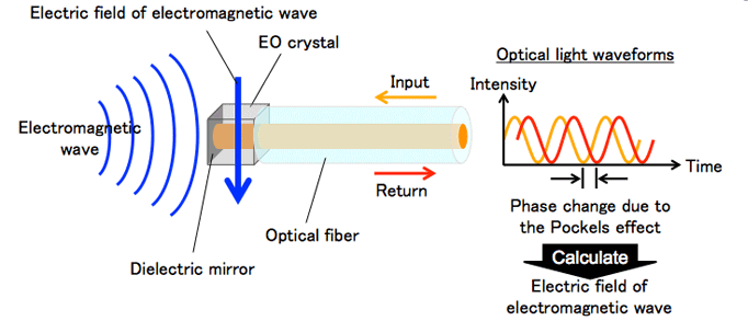
Figure 2: Conventional Electric-field Probe and EO Probe
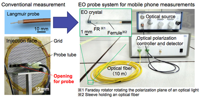
Figure 3: Improvements in EO Probe
| (Issues in microwave plasma measurement) (1) Improvement of sensitivity stability | (Improvements) 16 % ⇒ 10 % |
| (2) Improvement of magnetic-field resistivity | 0.1 T ⇒ 0.8 T |
| (3) Improvement of thermal resistivity | 100 deg C ⇒ 1200 deg C |
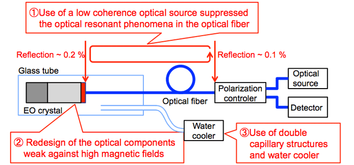
Figure 4: Plasma Electric-field Measurement System
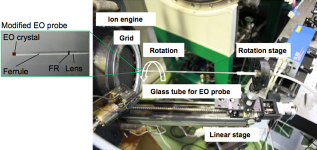
Figure 5: Measured Plasma Electric Field in Ion Engine
